How to Build Secure FortiGate Site-to-Site VPNs
Description
Configure FortiGate Site-to-Site VPN using IPsec tunnels with FW1/FW2 settings, routing, troubleshooting, and security best practices for secure connectivity.
Introduction
A site-to-site IPsec VPN creates a secure encrypted tunnel between two separate networks over the internet in a FortiGate Site-to-Site VPN setup. It allows devices at different locations to communicate securely as if they are on the same local network.
This type of VPN is widely used in enterprise environments within a FortiGate Site-to-Site VPN setup to connect headquarters, branch offices, remote buildings, data centers, and disaster recovery sites.
In a Fortinet FortiGate firewall, IPsec Tunnels provide enterprise-grade VPN deployment with full control over FortiGate Site-to-Site VPN setup and configuration.
- Phase 1 (IKE negotiation)
- Phase 2 (IPsec selectors)
- Firewall policies
- Static routes
This guide uses a real production-style FortiGate Site-to-Site VPN environment and explains every important configuration detail for both beginners and professionals.
Scope
This article explains the complete configuration of a route-based FortiGate Site-to-Site VPN using IPsec Tunnels between two FortiGate firewalls.
The VPN securely connects:
- FW1 (HQ):
192.168.111.0/24 - FW2 (Branch):
192.168.112.0/24
This guide covers mirrored configuration on both FortiGate devices for a stable and secure FortiGate Site-to-Site VPN bidirectional communication.
This guide covers
- VPN Wizard deployment
- Phase 1 configuration
- Phase 2 configuration
- Local and remote subnet mapping
- Firewall policy configuration
- Static routing
- VPN verification
- Packet flow explanation
- Troubleshooting and debugging
- Enterprise security best practices
This guide does NOT cover
- SSL VPN
- ADVPN
- Hub-and-spoke VPN
- Dynamic routing over VPN (OSPF/BGP advanced design)
- SD-WAN VPN orchestration
Real Environment Topology
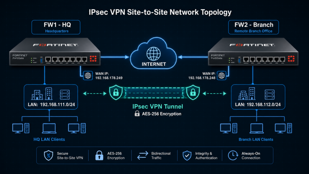
FW1 (HQ / Site A)
| Parameter | Value |
|---|---|
| Tunnel Name | To_FortiGate2 |
| WAN IP | 192.168.178.249 |
| Local Network | 192.168.111.0/24 |
| Remote Network | 192.168.112.0/24 |
FW2 (Branch / Site B)
| Parameter | Value |
|---|---|
| Tunnel Name | To_FortiGate1 |
| WAN IP | 192.168.178.248 |
| Local Network | 192.168.112.0/24 |
| Remote Network | 192.168.111.0/24 |
What is a Site-to-Site IPsec VPN?
A site-to-site VPN builds a permanent encrypted tunnel between two LAN networks.
In this deployment:
- FW1 protects the
192.168.111.0/24network - FW2 protects the
192.168.112.0/24network
Traffic between these networks is encrypted before crossing the internet.
Without VPN:
- Traffic travels unencrypted
- Data can be intercepted
- Networks remain isolated
With VPN:
- Data is encrypted
- Communication is secure
- Both sites communicate privately
Important Configuration Rule
All VPN settings must be mirrored on both FortiGate devices.
This means:
- The local subnet on one firewall becomes the remote subnet on the other firewall
- Phase 1 settings must match exactly
- Phase 2 settings must match exactly
- The pre-shared key must be identical on both sides
If these settings do not match, the tunnel may fail to establish or traffic may not pass.
Site A vs Site B Mirror Configuration Table
| Parameter | FW1 (HQ) | FW2 (Branch) |
|---|---|---|
| VPN Name | To_FortiGate2 | To_FortiGate1 |
| WAN IP | 192.168.178.249 | 192.168.178.248 |
| Local Subnet | 192.168.111.0/24 | 192.168.112.0/24 |
| Remote Subnet | 192.168.112.0/24 | 192.168.111.0/24 |
| IKE Version | IKEv2 | IKEv2 |
| Encryption | AES256GCM | AES256GCM |
| Authentication | SHA256 | SHA256 |
| DH Group | 14 or above | 14 or above |
| PFS | Enabled | Enabled |
| NAT Traversal | Disabled | Disabled |
| DPD | Enabled | Enabled |
| NAT Policy | Disabled | Disabled |
Pre-Requirements
Before configuring the VPN, verify the following:
1. Internet Connectivity
Both FortiGate firewalls must have internet access.
Verify connectivity using:
execute ping 8.8.8.8
2. Reachable WAN IP Addresses
Each firewall must be able to reach the peer WAN IP.
FW1:
192.168.178.249
FW2:
192.168.178.248
3. Non-Overlapping Networks
The LAN subnets on both sites must be different.
Correct:
192.168.111.0/24192.168.112.0/24
Incorrect:
- Same subnet on both sides
4. Required Ports
The following ports/protocols must be allowed:
| Protocol | Purpose |
|---|---|
| UDP 500 | IKE Phase 1 and Phase 2 negotiation |
| ESP (Protocol 50) | Encrypted IPsec VPN traffic |
Note:
UDP 4500 is required only when NAT Traversal (NAT-T) is enabled or when VPN peers are behind NAT devices. In this deployment, NAT Traversal is disabled, so UDP 500 and ESP are primarily used.
5. Time Synchronization
NTP should be enabled on both devices.
Incorrect system time may cause VPN negotiation failures.
Solution
Step-by-Step IPsec Tunnel Configuration
Step 1: Login to FortiGate GUI
Open a web browser and access the firewall management interface:
https://<fortigate-wan-ip>
Enter administrator credentials.
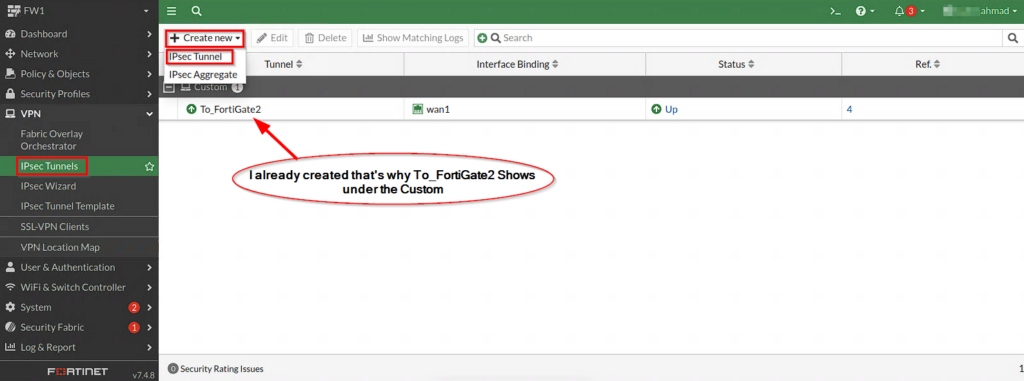
Step 2: Open IPsec Tunnels Configuration
Navigate to:
VPN → IPsec Tunnels
Select:
Create New
Choose:
Custom VPN Tunnel
Step 3: Configure Basic VPN Information
FW1 (HQ)
| Field | Value |
|---|---|
| VPN Name | To_FortiGate2 |
| Remote Gateway | Static IP Address |
| IP Address | 192.168.178.248 |
| Interface | wan1 |
FW2 (Branch)
| Field | Value |
|---|---|
| VPN Name | To_FortiGate1 |
| Remote Gateway | Static IP Address |
| IP Address | 192.168.178.249 |
| Interface | wan1 |
Step 4: Configure Authentication
Select:
- Authentication Method: Pre-shared Key
Enter a strong shared secret.
Example:
MyStrongVPNKey123!
The key MUST match on both FortiGate devices.
Step 5: Configure Phase 1 Settings
Phase 1 creates the secure management channel used to negotiate VPN parameters.
| Setting | Value |
|---|---|
| IKE Version | IKEv2 |
| Encryption | AES256GCM |
| Authentication | SHA256 |
| DH Group | 14 or above |
| Key Lifetime | Default |
| DPD | Enabled |
| NAT Traversal | Disabled |
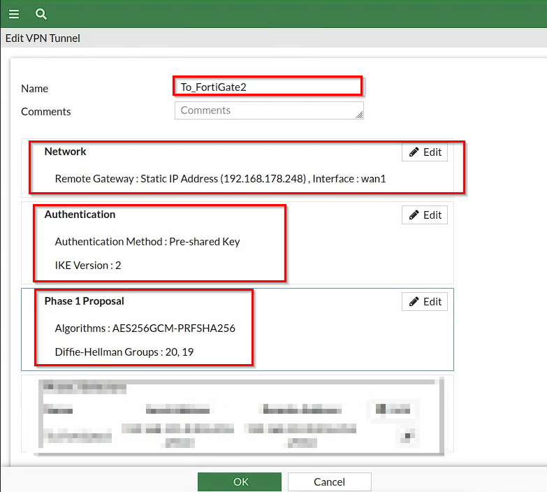
What happens during Phase 1?
During Phase 1:
- Both firewalls authenticate each other
- Encryption parameters are negotiated
- Secure IKE tunnel is established
If Phase 1 fails:
- VPN tunnel will remain DOWN
Step 6: Configure Phase 2 Settings
Phase 2 defines which traffic should be encrypted inside the tunnel.
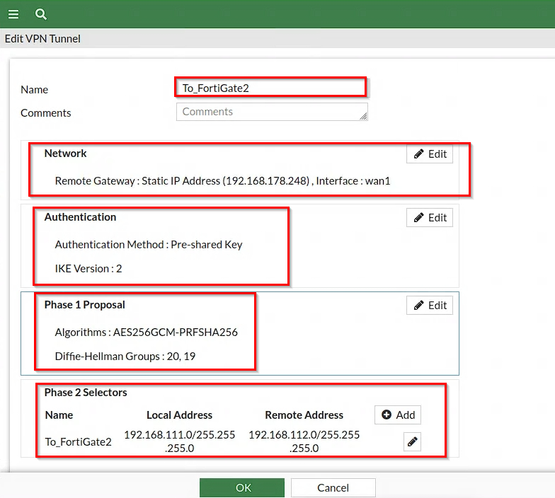
FW1 (HQ)
| Field | Value |
|---|---|
| Local Subnet | 192.168.111.0/24 |
| Remote Subnet | 192.168.112.0/24 |
FW2 (Branch)
| Field | Value |
|---|---|
| Local Subnet | 192.168.112.0/24 |
| Remote Subnet | 192.168.111.0/24 |
Important Note About Phase 2
Phase 2 selectors MUST be mirrored correctly.
Example:
FW1:
192.168.111.0/24 → 192.168.112.0/24
FW2:
192.168.112.0/24 → 192.168.111.0/24
If Phase 2 selectors are incorrect:
- Tunnel may show UP
- Traffic will NOT pass
Step 7: Firewall Policy Configuration
Create policies on BOTH firewalls.
Required Policies
LAN → VPN
Purpose:
- Allow internal users to access remote site
VPN → LAN
Purpose:
- Allow return traffic from remote site
Important NAT Setting
NAT must be DISABLED for VPN traffic.
Correct:
NAT: Disabled
Incorrect:
NAT: Enabled
Enabling NAT can break VPN communication.
Step 8: Static Route Configuration
Routes tell the firewall where remote networks are located.
FW1 Route
					Destination: 192.168.112.0/24
Device: To_FortiGate2
FW2 Route
					Destination: 192.168.111.0/24
Device: To_FortiGate1
Step 9: Bring Up the Tunnel
Generate traffic between both sites.
Example:
From FW1 LAN:
ping 192.168.112.xping 192.168.112.x
From FW2 LAN:
ping 192.168.111.x
VPN tunnels often establish automatically after traffic is detected.
Step 10: Verify VPN Status
GUI Verification
Navigate to:
VPN → IPsec Monitor
Tunnel status should display:
UP
CLI Verification
get vpn ipsec tunnel summary

Real Packet Flow Diagram
					FW1 (192.168.111.x)        FW2 (192.168.112.x)
        |                          |
        |--- UDP 500 (IKE) ------>|
        |<-- IKE Phase 1 SA ------|
        |--- Phase 2 Setup ------>|
        |<-- IPsec SA Reply ------|
        |==== VPN Tunnel UP ======|
        |--- ESP Encrypted ------>|
        |<-- Encrypted Return ----|
Troubleshooting
Tunnel DOWN
Possible causes:
- Wrong pre-shared key
- Wrong WAN IP
- Phase 1 mismatch
- UDP 500 blocked
- UDP 4500 blocked
Tunnel UP but No Traffic
Possible causes:
- Incorrect Phase 2 selectors
- Missing routes
- Missing firewall policies
- NAT enabled
One-Way Traffic
Possible causes:
- Missing reverse policy
- Missing return route
Intermittent Tunnel Drops
Possible causes:
- ISP instability
- MTU issues
- DPD mismatch
Useful Debug Commands
Enable IKE debugging:
					diagnose debug application ike -1
diagnose debug enable
Stop debugging:
diagnose debug disable
Notes and Tips
Use Strong Encryption
Recommended:
- AES256GCM
- SHA256
- DH Group 14+
Avoid weak algorithms.
Keep Firmware Updated
Updated FortiOS versions improve:
- Stability
- Security
- VPN compatibility
Use Descriptive Tunnel Names
Good example:
HQ-to-Branch-VPN
Bad example:
VPN1
Enable Logging
VPN logging helps during troubleshooting and monitoring.
Backup Configuration
Always backup configuration before major changes.
Security Best Practices
- Use IKEv2 only
- Use strong pre-shared keys
- Disable unnecessary services
- Restrict management access
- Enable logging and monitoring
- Use modern encryption algorithms
- Regularly review firewall policies
Conclusion
This FortiGate site-to-site IPsec VPN configuration securely connects:
- FW1 (HQ):
192.168.111.0/24 - FW2 (Branch):
192.168.112.0/24
Using mirrored Phase 1 and Phase 2 configurations ensures secure and stable encrypted communication between both networks.
FortiGate IPsec Tunnels provide enterprise-grade security, flexibility, and reliable site-to-site connectivity. while still providing enterprise-grade security and flexibility.
FAQ
Why is my VPN tunnel down?
Common causes include:
- Incorrect pre-shared key
- Wrong WAN IP
- Blocked UDP 500/4500
- Phase 1 mismatch
Why is the tunnel UP but traffic is not passing?
Usually caused by:
- Incorrect Phase 2 selectors
- Missing firewall policies
- Missing static routes
- NAT enabled on VPN traffic
Do both FortiGate firewalls require configuration?
Yes. Site-to-site VPNs require mirrored configuration on both sides.
What is the difference between Phase 1 and Phase 2?
Phase 1:
- Creates the secure management tunnel
Phase 2:
- Defines which traffic is encrypted
Should I use IKEv1 or IKEv2?
IKEv2 is recommended because it offers:
- Better security
- Faster negotiation
- Improved stability
Why should NAT be disabled for VPN traffic?
NAT changes source addresses and can break encrypted VPN communication.